GAIN AND EIRP
RJ Burkholder, Research Professor of Electromagnetics and RF at The Ohio State University1
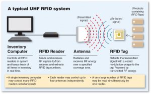
In the last blog I maintained that the antenna is the most important part of a UHF RFID system (see figure below). This is because the computer software, reader, and RFID tag are quite optimized now, and often outside the control of the system designer/integrator. Performance improvements must come from the antenna and its deployment.

A typical UHF RFID inventory system
Before getting into the fine art of antenna deployment, it is first necessary to understand the basic principles of how antennas work and how the electromagnetic field radiated by an antenna fills and penetrates a given space. The main issues are polarization, fading, attenuation, gain, maximum EIRP (effective isotropic radiated power) and diversity. A good understanding of these issues will aid the designer in selecting the type and number of antennas, and where to put them for optimum performance.
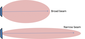
The most basic characteristic of an antenna is its gain. This number is defined as the amplification of the antenna compared with an antenna that radiates equally in all directions. Hence, the units of gain are often dBi, which means “decibels relative to isotropic”. By definition, an antenna that has greater than 0 dBi gain does not radiate isotopically (the same in all directions), but has a gain pattern, sometimes referred to as its antenna pattern, or directivity pattern, as illustrated below.

Gain patterns of a broad beam antenna and a narrow beam antenna.
The narrow beam antenna has a higher gain than the broad beam antenna, but a much smaller angular coverage. This is because both antennas radiate the same total power, and the gain pattern determines how this power is distributed. (Note that I am assuming here for simplicity that the antennas are 100% efficient. In other words, all of the power input to the antenna is radiated.) Our first principal is this:
- For the same amount of radiated power, increasing the gain of an antenna decreases the angular coverage.
A typical patch-type RFID antenna has a gain of about 6 dBi and looks like the broad beam pattern above. The designer might like to improve the read range by using an antenna with a higher gain, like the narrow beam antenna above, if angular coverage is not important. Unfortunately, it’s not that simple, but not because of the antenna.
This brings us to a very important concept in UHF RFID, namely, Effective Isotropic Radiated Power (EIRP). EIRP is defined as the amount of power that a theoretical isotropic antenna would emit to produce the peak power density observed in the direction of maximum antenna gain. For example, a typical RFID reader generates 30 dBm (decibels relative to a miliwatt) of RF power. Connecting a patch antenna with 6 dBi gain results in an EIRP of 36 dBm (30+6).
It so happens that 36 dBm is the maximum EIRP allowed by the FCC for electronic devices in the UHF RFID band. Now suppose I want to use the narrow beam antenna shown above, which has a gain of 12 dBi for example. Then the EIRP becomes 42 dBm which is over the FCC limit. I will have to reduce the reader power to compensate. Our second principal is this:
- Increasing the gain of an antenna also increases the EIRP, which is limited by the FCC.
Therefore, for maximum read range it doesn’t necessarily help to use a high gain antenna because you will have to reduce the RF power. The only advantages of a high gain antenna in RFID is to get a good read range with minimal power, or to focus a beam in a limited coverage area.
Next blog: Antenna basics – polarization: does it really matter?
The opinions expressed on this webpage are the author’s and do not necessarily represent the opinions of The Ohio State University.

